2015年5月7日星期四

What Are Printed Circuit Boards Used for?

In the early days of electronics, when vacuum tubes were king,
all of the various components that made up an electronic device were connected together by soldering them either to each other or to terminal strips and tube sockets. Today, printed circuit boards have made connecting components simpler and cheaper.
What Are PCBs?

Printed circuit boards (PCBs) are thin boards made from an insulating material, with a metal coated surface, sometimes on both the top and bottom. Etches are made in the metal with acid to create pathways for electricity to travel among various components which are surface mounted on the board with solder.

PCB Advantages

The invention of printed circuit boards is one of the factors that has enabled electronic circuits to be smaller, more compact, and contained on a convenient, rugged board. Holes drilled into circuit boards allow components such as resistors and capacitors to be inserted and soldered through automation.

PCBs Are Everywhere

Today, just about every electronic appliance in your home contains a printed circuit board of some type: computers, printers, televisions, stereos, musical instrument amplifiers and synthesizers, digital clocks, microwave ovens, telephone answering machines and even cell phones.

PCBs In Computers

The "motherboard" in a computer is the main printed circuit board that is the heart of a computer. Other circuit boards inside a computer performs functions such as RAM (random access memory), power supplies, modems and video "cards."

The Works in a Drawer

Motorola's Quasar TVs were among the first to use removable printed circuit boards, designed for quick in-home repair.

2015年5月5日星期二

The characteristics of the electric vehicle power supply circuit board

At present there are two kinds of electric cars, is a kind of electric bicycle and motorcycle, is a kind of electric cars.And their driver is driven by the power supply, thus produce the power circuit board.

Power supply circuit board is outstanding requirements is a high reliability requirements, coating symmetry degree is high, the general has four features:

1, small volume, light weight, volume and weight for 1/5-1/10 of SCR power supply for you plan, expansion, mobile, maintenance and installation.

2, good energy saving effect: the adoption of high frequency transformer, switch power supply conversion efficiency is greatly increased, under normal circumstances a silicon controlled rectifier equipment to improve efficiency more than 10%, the load rate was below 70% when a silicon controlled rectifier equipment to improve efficiency more than 30%.

3, output, high stability, due to the system response speed (microsecond), for, and load change with a strong adaptability for electricity network output accuracy can be better than 1%.Switch power supply, high working efficiency, and high control precision, so to improve the quality of the product.

4, output waveform modulation: easily due to the high working frequency, the output waveform adjustment relatively low processing cost, can be convenient to make in accordance with the technological requirements of the user to change the output waveform.So for working site to improve work efficiency, improve the processing quality of the product has strong effect.

Increasingly competitive in technology today, Wen Defeng technology co., LTD, increasing investment in technology research and development, to cooperate with clients for all kinds of printed circuit board of high, refined, sharp demand, the company introduces Germany, France and other places of advanced production equipment, relying on scientific management, has trained a number of highly qualified professional talent team, at the same time with high quality products, reasonable price, fast delivery time, good after-sales service to serve the broad masses of customers, high quality products to our customers to provide safe and reliable.

For more information, pls kindly contact me: www.wonderfulpcb.com

Flex PCB - What is Flex PCB

Flexible PCB and the birth and development of the PCB, Rigid-Flex PCB gave birth to this new product. Therefore, Flex PCB is flexible circuit board and rigid circuit boards, after lamination processes, according to the relevant process requirements together, forming characteristics have FPC PCB board characteristics.

1.Flex PCB - Production Process:

Because Flex PCB is a combination of FPC and the PCB, Flex PCB production should also have the FPC PCB production equipment and production equipment. First, the combination of soft board electronics engineer to draw a line and shape according to demand, then, can be issued to the Flex PCB production plant, through CAM engineers relevant documents for processing, planning, and then arrange FPC production line production need FPC, PCB production line to produce PCB, after these two soft board and hard board out, according to the planning requirements for electronic engineers, the FPC and PCB through seamless lamination lamination machine, and then through a series of detailed links, ultimately process the Flex PCB. A very important aspect should Flex PCB difficult, more details before shipping, are generally required to conduct the inspection, its value is relatively high, so as not to let the supply and demand sides related loss of interest.

2. Flex PCB - Advantages and Disadvantages:

Advantages: FPC Flex PCB along with features and characteristics of the PCB, so it can be used in some special requirements of the product among the region has some flexibility, but also have a certain rigidity region of the internal space-saving products reduce the volume of the finished product, improve product performance is very helpful.

Cons: Flex PCB production process many, difficult to produce low yields, cast materials, manpower more, so its price is more expensive, relatively long production cycle.

3. Flex PCB - Related Applications
Flex PCB's characteristics determine its application in all areas covered by FPC PCB applications, such as:

1.Mobile telephone

2.Keypad and side buttons, etc.

3.Computer and the LCD screen
Such as motherboards and display
a.CD Walkman
b.Drives
c.NOTEBOOK.

4. New Uses
Components of a hard disk drive (HDD, hard disk drive) suspension circuit and xe packaging board, etc.

2015年4月28日星期二

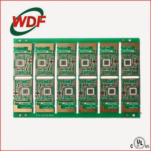
PCB single panel process

Why we use PCB single panel process?
The primary reason for having your boards delivered in an array is to make automated assembly faster and less expensive. Running an array of boards through a pick-and-place machine is far more efficient than sending them through one at a time. Arrays are also desirable because they allow the addition of tooling rails, tooling holes, and fiducials, all of which help your assembler.

PCB single panel process

Cutting→drilling printed circuit→the entire board gold→etching→inspection and printing solder→tin spraying→printing character→forming and finished product inspection→rosin and packaging

Process HASL process PCB double-faced board

Cutting, drilling, copper deposition, board ( thickened copper ), image transfer, electrical copper tin, tin, inspection and printing etching resistance welding, seal character, spray tin, forming, testing, product inspection and packaging

Process HASL process of PCB multilayer board

Open the material, inner layer, inner layer etching, Inner Inspection and melanization ( brown )→→→→plate laminated shooting drill electric ( thickened copper ), pattern transfer ( outer ), electrical copper tin, tin, inspection and printing etching resistance welding, seal character, spray tin, forming, testing, product inspection and packaging

PCB multilayer board finger + HASL process

Open the material, inner layer, inner layer etching, Inner Inspection and melanization ( brown )→→→→plate laminated shooting drill electric ( thickened copper ), pattern transfer ( outer ), electrical copper tin, tin, inspection and printing etching resistance welding, seal characters, gold finger, spray tin, forming, testing, product inspection and packaging

FPC single panel process:

Cutting, drilling, dry film lamination, counterpoint, exposing, developing, etching, stripping, surface treatment, paste coating and pressing, curing and surface treatment, ENIG, seal characters, cutting, electrical measurement, punching, final inspection, packing and shipment

FPC double-faced board process:

Cutting, drilling→ PTH →plating, pretreatment, dry film lamination, counterpoint, exposing, developing, figure plating, pretreatment, dry film lamination, exposure, developing, etching, stripping, surface treatment, paste coating and pressing, curing and ENIG, seal characters, cutting, electrical measurement→punching, final inspection, packing and shipment of stripping,

Technological process of FPC multilayer board

Open the material, inner layer, inner layer etching, Inner Inspection and melanization ( brown )→→→→laminated targeting drilling deposit copper and board ( thickened copper ), pattern transfer ( outer ), electrical copper tin, tin, inspection and printing etching resistance welding, chemical nickel gold, seal characters, forming to test, product inspection and packaging

Rigid-flex pcb node ( FPC ) plate process

Open the material, inner layer, inner layer etching, Inner Inspection and melanization ( brown )→→→→laminated targeting drilling deposit copper and board ( thickened copper ), pattern transfer ( outer ), electrical copper tin, tin, inspection and printing etching resistance welding, chemical nickel gold, seal characters, forming to test, product inspection and packaging.

2015年4月26日星期日

FPC Assembly

Nowadays, technology is already very mature to rigid Printed circuit board, however, many problem may be faced by operator during SMT to flexible PCB.
1 False soldering, short soldering,Tin beads.
2.The Reason is due to the hardness of  raw material of FPC(Flexible printed circuit) caused, FPC is out of shape when meet the hot air and high temperature in reflew machine. Lead the wave shape to FPC, and the slop to FPC pads, then cause the flow of molten tin (liquid tin under high temperature), which cause False soldering, short soldering,Tin beads.(The main reason is the hardness of FPC). So if make the hardness of FPC into the same situation as rigid printed circuit board, and all soldering problem to FPC can be solved. The condition is you should know the SMT process to PCB. And then improve the hardness of Flexible Printed circuit into with the same hardness as rigid PCB, and then FPC SMT can be realized. And some problem, like no fix hole, no mark point, or the FPC is over long, which are the fault of designer, and it is also hard to be solved even to rigid PCB SMT. And NG rate can be only reduced based on personal experience or device independence.

According to above comment, the main solution is to improve the hardness of FPC the same as hardness of rigid PCB.

B. How to realize stable soldering to FPC
How to get the stable FPC (flexible circuit board) to the rigid PCB welding effects depends on the degree of hardness.
Methods: using jigs(carrier, handling plate) to make FPC perform as rigid board during SMT.

Below is the instruction of Magnetic reflow soldering tray
The material
1. Choose imported alloy material: good flatness, stable performance under high temperature
2. High temperature resistant magnet (300 degrees) to ensure permanent magnet during reflow soldering process.
3.The special steel, with magnetic treatment and good elasticity, and no deformation under high temperature.
4.Performance
(1) Because the flatness to FPC surface cause from the steel pressure l, it can reduce the flow of solder tin during reflow, which can ensure the good quality of soldering and reduce the NG soldering at meanwhile.
(2) Ensure the life of tray when choosing tray material.
(3) Easy and convenient operation with high stability.
(4) Heat insulation, prevent the FPC from deformation
There’s no special requirement to the composition of solder paste of FPC, the size of the tin ball particles and the amount of metal content, etc will be subject to if there is narrow space of IC pins on FPC, BUT FPC has high performance requirements to the solder paste printing, solder paste should has good thixotropy, solder paste should be able to easily be printed , demoulding and can be firmly adhere to the surface of FPC, there will be no mold release lead the hole in stencil filled with tin or such as collapse after printing.

     Because FPC fixed on the pallet before SMT,  and the FPC with high temperature heat-resistant pressure-sensitive adhesive tapes for purpose of location, which make its planar inconsistencies, thus FPC printing surface is unlikely to be as smooth as rigid PCB and the same consistent on thickness and hardness, so operator should not use a metal scraper, and should use the polyurethane scraper which with hardness of 80-90 degree.

 Solder paste printing machine is best to be with the best optical positioning system, otherwise will have great influence to printing quality, FPC although fixed on the load board, however, there always be small space between FPC and the load board, this is the biggest difference as rigid PCB board, thus the equipment parameters’s setting will also has great influence to the printing effect.

    Printing stations is also the key location to prevent FPC from being smudgy, need to wear glove then can go ahead for operation, at meanwhile,  workstation should be kept clean, stencil should be frequently wiped to be clean, to prevent the solder paste to pollute the gold fingers and gold plated key button.

Control of FPC SMT

According to the properties of the products, components quantity and efficiency of mounting, it is OK to adopt high-speed placement machine for SMT. Because every piece of FPC has positioning with fiducial MARK, therefore, there’s no big difference on surface mounting technology between FPC SMD mounting and rigid PCB SMD mounting. It is important to note that although the FPC are fixed on the load board, but its surface can’t be the same flatness like rigid PCB board surface, local space must  exist between FPC and load board, so, the height of suction nozzle’s dropping, compression of blowing should be exactly setted.  On other side, most bare FPC performance as panel; format, and the rate of good finished product relatively low, so it if normal that there’re part of pieces with not good quality, which request recognition function on BAD MARK to SMT machine, otherwise, when mounting FPC panel with the status of not all pieces are good, will show low efficiency.

2015年4月24日星期五

WonderfuI Printed Circuit Board

     On the insulating substrate, according to a predetermined design, made of printed wiring assemblies, printer, or combination of both conductive patterns, known as a printed circuit. On the insulating substrate, the electrical connection between the conductive patterns provided components, known as printed wiring. It does not include printed components. Printed circuit or printed circuit board called the finished printed circuit board, or PCB, also known as printing plates used in printing plates in accordance with rigid or flexible substrates can be divided into two categories: rigid printed scrubbing brush and a flexible printed board. this is also rigidly --- flex printed board has occurred according to the conductor pattern layers can be divided into single-sided, double-sided and multilayer printed board and the entire outer surface of the conductor pattern surface of the substrate on the same plane printed board, called flat printing plate.
     After the electronic equipment used printing plates, printing plates because of similar consistency, thus avoiding the manual wiring errors, and can realize automatic insertion of electronic components or mount, automatic soldering, automatic testing to ensure the quality of the electronic equipment to improve labor productivity, reduce costs, and ease of maintenance. printing plates from development to single-sided, multi-layer and flexible, and still protect the respective trends. due to continuous high-precision, high density and high reliability direction, shrinking volume, reduce costs, making printing plates in the future development of the electronic device, remains strong vitality.
     FR-4 (flame resistant laminated sheet), is based on "fiberglass cloth" as the backbone of impregnation liquid flame resistance "epoxy" as a binding agent made the film, and then laminated plates made of various thickness. The so-called V-1 refers to 0.5 inches wide and 5 inches long, informal sample thickness of copper-free glass epoxy substrate of the order of 45 ° oblique after burning flame burning on a particular, and that is to remove the source of fire measured in seconds of its spread, let it put out before making a whole continued to burn. After ten consecutive test firing, the total number of seconds to less than 250 seconds were spread called V-1 grade FR-4, less than 50 seconds are known as V-0 grade FR-4.

Sophie Deng
_______________________________________
Wonderful PCB Limited
NO.32A,Building NO.1, XianDaiC hengHuaTing,ChuangYeRoad|NanShan District,ShenZhen City 518054|  China  T +86-755-86229518-806 | F  +86 755 2607 3529|  e  wonderful08@wonderfulpcb.com |
w  www.wonderfulpcb.com  | Skype:wonderful-07   |                                                  
Welcome to our trading shows:
1.Booth: L32,Expo Electronic 2013,Apr.10-12th in CROCUS EXPO,Moscow,Russia
2.Booth: 11J36, HK Global sources  Apr.12-15th, 2013 Asia World-Expo, Hong Kong
3.Booth: 9J35, HK Global sources Oct.12-15th,2013 Asia World-Expo, Hong Kong
4.Booth: 70206, CES  2014  Jan,8th-11th in Las Vegas, USA

2015年4月23日星期四

Worldwide Semiconductor Sales Expected to Reach $358 Billion in 2015

Worldwide semiconductor revenue is forecast to reach $358 billion in 2015, a 5.4 percent increase from 2014, but down from the previous quarter's forecast of 5.8 percent growth, according to Gartner, Inc. The market is being driven by strong growth in application-specific standard products (ASSPs) in smartphones, along with DRAM and NAND flash in ultramobiles and solid-state drives (SSDs).

"Semiconductor revenue growth in 2015 is expected to slow from the 7.9 percent growth experienced in 2014 as DRAM returns to more traditional price reductions and the industry burns off excess holiday inventory," said Jon Erensen, research director of Gartner. "DRAM pricing was unusually firm in 2014 due to short supply, which propelled DRAM to be the fastest-growing device type in 2014 with 31.7 percent revenue growth. DRAM supply and demand will be in line in 2015, driving bit pricing down a more traditional 16.8 percent and reducing annual DRAM revenue growth to 7.7 percent."

From an application point of view, smartphones, SSDs and ultramobiles will see the largest dollar increases. In 2015, compute applications will continue to be the largest market for semiconductors, followed by wireless and consumer applications. Combined, these three device categories represent more than two-thirds of total semiconductor revenue and have the most influence on the overall strength of the semiconductor market.

However, in 2015, the industrial electronics segment is expected to outperform overall semiconductor market growth and other electronic application categories with revenue growth of 9.1 percent. The growth will be driven mainly by LED lighting applications for industrial and residential purposes and smart city projects. In addition, the Internet of Things (IoT) will continue to drive very strong unit growth in 2015 and beyond.

Following industrial applications, wireless applications — driven mainly by mobile phones — will be the next biggest growth market for semiconductors in 2015. However, the 2015 revenue growth forecast for wireless applications, and specifically mobile phones, remains the same as the previous quarter's forecast.

"While mobile phone semiconductor sales will remain robust, driven by the accelerating shift to smartphones and 4G Long Term Evolution, there is concern that weak sell-through for other electronic equipment categories will result in higher inventory levels and drag down semiconductor sales in the first quarter of 2015," said Mr. Erensen.

2015年4月22日星期三

Global And China FPCB Industry Report, 2014

In 2013, flexible PCB board industry enjoyed a high-speed growth with the market size approximating USD12.03 billion, up 16.2% from the level in 2012. The South Korean vendors developed rapidly and were excessively upbeat about the industry’s outlook, aggressively expanding capacity starting from the very beginning of 2012. As a result, most of new capacity was available in Q2 2013. However, the FPCB companies in South Korea without diversified customers, were heavily dependent on the key accounts such as Samsung and LG, thus making them less competitive during negotiations. Therefore, these vendors cut the prices steeply in Q4 2013, sending them into price war.

In 2014, price decline continued to deteriorate, which led to a sharp fall in revenue of South Korean vendors. The implications of high-speed capacity expansion are high fixed costs, which would thus result in a plunge in profit margin. It is projected that the revenue of INTERFLEX, a leading South Korean FPCB company, would tumble by 50%, and its operating margin would record a 27% loss in 2014 in contrast to no-profit-no-loss in 2013. Additionally, affected by the order shift of Apple, the company has hardly received any orders from Apple in 2014.

Another pressure for the vendors in South Korea came from the depreciated yen, and the won appreciated against the yen. However, the Japanese products have better performance; coupled with the reduced prices bought on by yen depreciation, they are more competitive.

Apple shortened the supply chain, giving more of its orders to the vendors in Taiwan, which resulted in a fall in revenue of M-Flex, at an estimated 20% drop in 2014. And as the losses expand, M-Flex’s operating margin is expected to slip from -8.4% in 2013 to -11.8%.

Despite a substantial decline in revenue of the South Korean vendors, the biggest customer of FPCB market—Apple did not bring down the purchase price. Meanwhile, the new iPhones have bigger size and therefore need more FPCBs. Consequently, the vendors in Taiwan and Japan saw a big increase in revenue, thereby filling in the vacuum. We predict that in 2014 the market size of FPCB worldwide reached USD12.608 billion, up 4.8% from 2013.

Of the Taiwanese vendors, ZDT generated the most revenue. ZDT under Hon Hai obtained more of the orders from Apple. It is forecasted that its revenue will jump by 55% to USD1.518 billion in 2014, overtaking Japan’s SEI as the world's second. In contrast, the world’s first NOK reduced the capacity in Japan, instead expanded the capacity in Thailand and Mainland China, which helped not only substantially increase its revenue but also rapidly turn out of red. At the same time, the global HDD market tends to be stable, with the shipments rising mildly from 2013. The HDD for FPCB is the main product of NOK, an Apple's leading supplier.

We project that in 2015 smartphones will present a slowing growth, tablet PCs will begin to decline, notebook computers will grow slightly or be flat. Moreover, LCD-TVs are expected to grow by a small margin. And wearable devices are very likely to rise significantly, but its application of FPCB is too small to fuel the market. In 2015, it is more than likely that LCD-TV will be the mainstay to drive the market. And after 6-8 years of popularization, LCD-TV is expected to undergo a boom of TV set replacement. And consumers will choose 4K TV with higher resolution or change the original smaller 32-37 inch television to 40-42 inch television.

We expect that it will be very hard for the South Korean vendors to reverse the downtrend when Samsung’s mobile phone shipments slow down and its LCD shipments are falling with losses. It is more likely that the South Korean vendors will suffer collapse, while the companies from Japan and China’s Taiwan will benefit from it, especially Japanese ones that had improved the competitiveness after the repeated depreciation of yen.

2015年4月17日星期五

Separating the Best From The Rest


Do you know how to find a superior electronics contract manufacturing company? Too many small to mid-sized electronics businesses make the mistake of basing their partnership decisions on little more than the lowest bid offered. This, however, can be a fatal mistake. In all cases, you'll get what you pay for in terms of quality of components, parts, production value, and services. As a result, it's important that you have a concrete set of criteria that will help you to pinpoint a "zero" from a "hero" and ensure that you make the best possible decision when hiring a contract manufacturing service. This list of characteristics and qualifications will help to get you on your way to a successful partnership.

History & Experience
For obvious reasons, it's in your best interest to look for a business that is well established. A contract manufacturer that has been able to hold its own throughout the years has done so by proving itself again and again as a reliable service that produces high quality designs and PC board assembly serves. Be sure to investigate how many years the manufacturer has been in operation, and feel free to inquire about their level of industry expertise.

Age & Type of Equipment
You want a contract manufacturing company that is able to quickly and efficiently design and assemble your PC boards, and making use of advanced technologies is one of the best means of accomplishing this goal in the most cost-effective manner possible. Feel free to ask your prospects about the types of machinery and equipment that they utilize, and take a look at what type of condition the units are in. Are they well maintained? This is a good sign that the business is reputable.

Operator Certifications
The company's employees who will be working on your boards should be either certified on the latest industry standards, or else working towards their certifications. This indicates a level of knowledge and expertise, and also portrays the worker's passion and interest in providing solid work and superior boards.

Quality Standards
ISO9001-2008 should be the minimum industry standard that the contract manufacturer has established. It's important to find out whether or not the company has reached these and other important standards for quality and safety throughout the board design and production process.

Aluminum PCB Product Repairs
Should something go wrong with a board, will the contract manufacturer be there to help you out with fulfillment services? In order to save yourself from a lot of stress and monetary losses, it's wise to seek out a company that will take the time to troubleshoot and repair problems so that you don't have to shell out the money on warranty replacements.

Unless your electronics contract manufacturer meets all of these criteria, it's in your best interested to move on with your search so as to find the best fit for the job.

PCB Prototype Assembly Services

The evolution of our world's technology is truly astounding. In the past decades, we've made great leaps and bounds in terms of what our electronic devices are capable of accomplishing, and things are only getting better. Technological engineers and electronics designers are continuously dreaming up new ways to improve existing products, as well as completely original ideas for simplifying everyday life and tasks. But how does this process occur, exactly?

Every bit of technology - from the smallest, consumer electronic gadget to complex healthcare and aerospace units - begins with an idea. From here, plans can be made to develop a working prototype in order to test the capabilities of the device and to determine whether the idea is worth investing in, or how it can be further expounded upon in order to make it more operable, functional, and efficient. Every step in designing and assembling the prototype is essential to enabling the simple dream to become a reality. To give you a better idea of the process, this post will walk you through the life cycle of a prototype.

The Idea Phase
At this point, you or one of your clients may have a thought for how to improve an existing unit or device, or for creating something brand new. Here, you discuss what the PC board should be able to accomplish, what the functions of the device should be, and the sizing requirements for the unit and, therefore, for the board.

The Design Phase
Once you have a good idea but any size constraints for the board and know what it is that you want to be able to do with it, you can begin actually planning and designing the schematics for the PCB development for the prototype. You'll need to consider the necessary components for achieving your objectives, and how these will factor into the layering and thickness of the board, as well as any budgetary concerns.

The Assembly Phase
After the design schematics have been tested out and approved, the board is ready to be assembled for the working prototype. In order to ensure that the PCB will be functional, efficient, and effective, it's important that all settings are properly calibrated (for automated processing), and that the use of the most advanced equipment is utilized so that every component is laid out and connected with the utmost precision, while still maintaining speed.

The Testing Phase
After the board has been assembled, it will need to be subjected to testing. First, you or your contract manufacturer will need to analyze the PCB to ensure that it's actually functioning in accordance with the client's specifications and the design schematics that were previously drawn up. Any inconsistencies or errors will need to be troubleshooted and addressed before the board is presented to the client. From here, the client may want to run their own set of tests, and actually test out the use and functionality of the device as a working whole before making a decision about ordering a larger batch.

The Adjustment Phase
After testing out the initial prototype, you or your client may notice certain areas that could be improved upon, which would make the end product more efficient and effective. After making not of these areas, you may need to go back to the original specs and make some adjustments before mass assembling the final PC boards.

A Never Ending Cycle
Even after a prototype has been approved for mass production and has made its way to the end user, its evolutionary cycle is never actually complete. As technology advances, it will be discovered that the existing device can be improved upon, or even eventually replaced, by something better, but that's what makes the world of technology so exciting! As long as dreamers are coming up with new ideas, we'll be ready to take on the challenge of developing prototypes that may end up changing the world.

2015年4月16日星期四

SUPO INDUSTRIAL CO., LIMITED

SUPO INDUSTRIAL CO., LIMITED has been serving the worldwide market since 2006, with global headquarters in Hong Kong with Oversea branch offices in the worldwide. High-quality and competitive price are the advantages of our rams, therefore, we have achieved good share of market in the business circle in and out of China.

We manufacture products in Shenzhen, HongKong and TP, we are have products line on computer memory modules, memory cards; memory ram, DDR & DDR2 & DDR3 for Desktop & laptops. Most products have attained CE and FCC certification.

We have a young and energetic professional work team to offer you excellent services.

Our culture is based on a long-lasting commitment to customer satisfaction. We are determined to produce the most advanced products with absolutely the lowest rate of return for every customer to receive the quality, performance and dependability they deserve.
Less